


Absolute hollow bore (blind) encoder,
CAN SAE J1939 WDGA 58E
Galvanic isolation
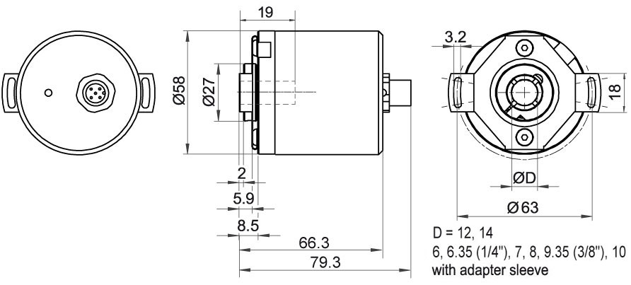
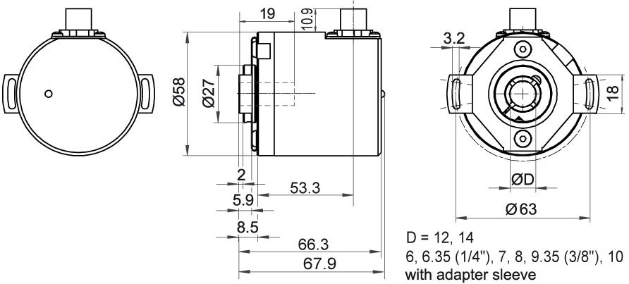
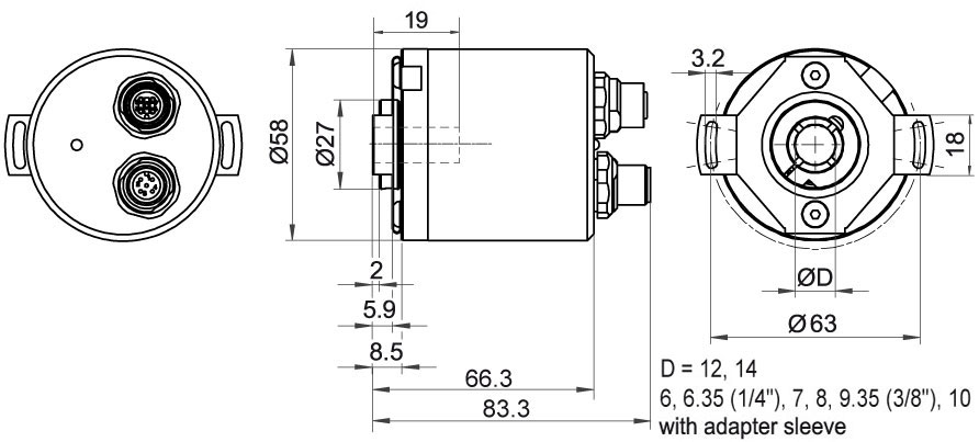
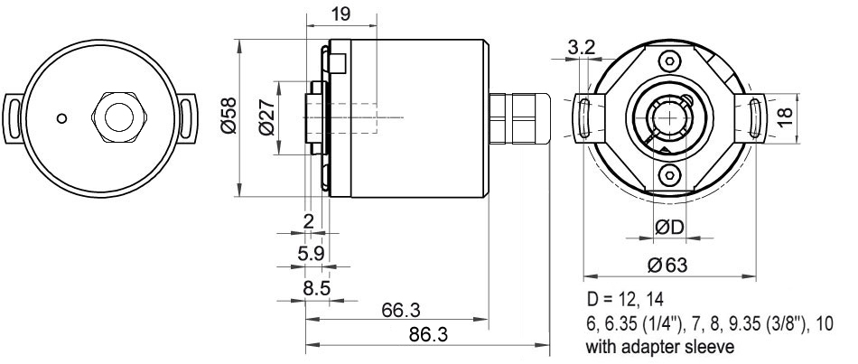
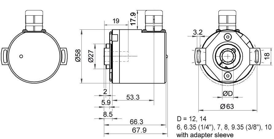
Housing: Ø 58 mm [2.283"]
16/32-bit Single-turn/Multi-turn;
Bore size Ø: 12 mm [0.472"],
14 mm [0.551"], 15 mm [0.591"];
with adapter sleeve Ø:
6 mm [0.236"], 6.35 mm [1/4''],
7 mm [0.276"], 8 mm [0.315"],
9.525 mm [3/8''], 10 mm [0.394"],
12.7 mm [1/2"]

- EnDra® Multiturn Technology: maintenance-free and environmentally friendly
- CAN SAE J1939 protocol
- Forward-looking technology with 32 Bit processor
- 2-colour-LED as indicator for operating condition
65.536 steps/360° (16 bit)
Multi-turn Resolutionup to 32 bit
Advice: with adapter sleeve
Shaft length: L: 17 mm [0.669"]
Insertion depth min.: 10 mm [0.394"]
Insertion depth max.: 19 mm [0.748"]
Max. Permissible shaft loading radial: 80 N [8.157 kp]
Max. Permissible shaft loading axial: 50 N [5.098 kp]
Advice: with adapter sleeve
Shaft length: L: 17 mm [0.669"]
Insertion depth min.: 10 mm [0.394"]
Insertion depth max.: 19 mm [0.748"]
Max. Permissible shaft loading radial: 80 N [8.157 kp]
Max. Permissible shaft loading axial: 50 N [5.098 kp]
Advice: with adapter sleeve
Shaft length: L: 17 mm [0.669"]
Insertion depth min.: 10 mm [0.394"]
Insertion depth max.: 19 mm [0.748"]
Max. Permissible shaft loading radial: 80 N [8.157 kp]
Max. Permissible shaft loading axial: 50 N [5.098 kp]
Advice: with adapter sleeve
Shaft length: L: 17 mm [0.669"]
Insertion depth min.: 10 mm [0.394"]
Insertion depth max.: 19 mm [0.748"]
Max. Permissible shaft loading radial: 80 N [8.157 kp]
Max. Permissible shaft loading axial: 50 N [5.098 kp]
Advice: with adapter sleeve
Shaft length: L: 17 mm [0.669"]
Insertion depth min.: 10 mm [0.394"]
Insertion depth max.: 19 mm [0.748"]
Max. Permissible shaft loading radial: 80 N [8.157 kp]
Max. Permissible shaft loading axial: 50 N [5.098 kp]
Advice: with adapter sleeve
Shaft length: L: 17 mm [0.669"]
Insertion depth min.: 10 mm [0.394"]
Insertion depth max.: 19 mm [0.748"]
Max. Permissible shaft loading radial: 80 N [8.157 kp]
Max. Permissible shaft loading axial: 50 N [5.098 kp]
Shaft length: L: 17 mm [0.669"]
Insertion depth min.: 10 mm [0.394"]
Insertion depth max.: 19 mm [0.748"]
Max. Permissible shaft loading radial: 80 N [8.157 kp]
Max. Permissible shaft loading axial: 50 N [5.098 kp]
Shaft length: L: 17 mm [0.669"]
Insertion depth min.: 10 mm [0.394"]
Insertion depth max.: 19 mm [0.748"]
Max. Permissible shaft loading radial: 80 N [8.157 kp]
Max. Permissible shaft loading axial: 50 N [5.098 kp]
Current consumption: typ. 100 mA
Power consumption: max. 1 W
LED signaling![]() Demonstration of the LED status signaling
Demonstration of the LED status signaling

| Description | |
|---|---|
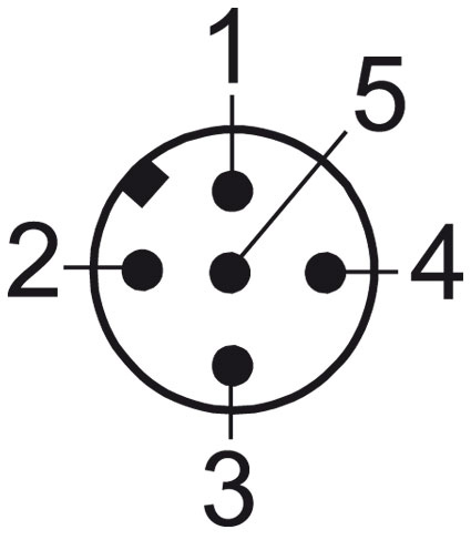
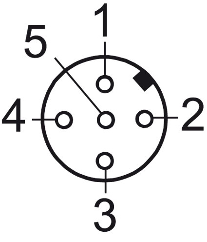
| CB5 | axial, 5-pin, shield connected to encoder housing |
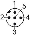

| Description | |
|---|---|
| CC5 | radial, 5-pin, shield connected to encoder housing |

| Description | |
|---|---|
| DB5 | axial, 5-pin, shield connected to encoder housing |


| Description | |
|---|---|
| L2 | axial, shield connected to encoder housing |
| (+) Vcc | BN |
| GND | WH |
| CANHigh | GN |
| CANLow | YE |
| CANGND shield | shield |

| Description | |
|---|---|
| L3 | radial, shield connected to encoder housing |
| (+) Vcc | BN |
| GND | WH |
| CANHigh | GN |
| CANLow | YE |
| CANGND shield | shield |

- Absolute encoders with flange Ø 36 mm / Ø 58 mm
- Single-/Multiturn (16/43)
- Ground-breaking technology 32 Bit processor
- Very high shaft loading, IP67
- EnDra® Multiturn technology: No gears, no battery
- QuattroMag® Singleturn technology: High precision +/- 0,0878°

- Incremental and absolute encoders
- Digital shaft copying
- Made in Germany
- Motorfeedback
- Position Measurement Systems


Shaft adapter WDGWA10M06
for thru-bore and hollow bore (blind) encoder Ø 10 mm
or couplings Ø 10 mm,
thread M6.

Shaft adapter WDGWA10M08
for thru-bore and hollow bore (blind) encoder Ø 10 mm
or couplings Ø 10 mm,
thread M8.

Shaft adapter WDGWA10M10
for thru-bore and hollow bore (blind) encoder Ø 10 mm
or couplings Ø 10 mm,
thread M10.

Shaft adapter WDGWA10M12
for thru-bore and hollow bore (blind) encoder Ø 10 mm
or couplings Ø 10 mm,
thread M12.

Shaft adapter WDGWA10M14
for thru-bore and hollow bore (blind) encoder Ø 10 mm
or couplings Ø 10 mm,
thread M14.

Shaft adapter WDGWA10M16
for thru-bore and hollow bore (blind) encoder Ø 10 mm
or couplings Ø 10 mm,
thread M16.

Shaft adapter WDGWA10M20
for thru-bore and hollow bore (blind) encoder Ø 10 mm
or couplings Ø 10 mm,
thread M20.

Adapter sleeves for bore size Ø 12 mm
for thru-bore encoder WDGI 58H and
hollow bore (blind) encoder WDGI 58E, WDGA 58E, WDGP 58E.
The encoder WDGA 58E CAN SAE J1939 galv. is also available with fixed 120 Ohm terminating resistor.

Here you find a list of our distributors worldwide