


WDG 58S
Shaft Encoder incremental,
Resolution: up to 25000 ppr,
Clamping flange: Ø 58 mm [2.283"]
Salt mist IEC 60068-2-11
Corrosion resistance
Shaft Ø: 10 mm [0.394"],
Protection rating: IP67 + IP69K, (high pressure / steam cleaning)
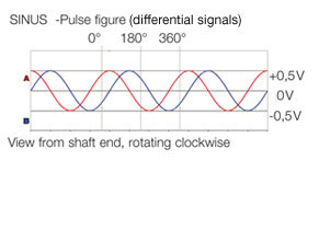
Signal shape: square-wave or sine/cosin,
Operating principle: optical.

Illustration similar
Highlights
- Resistence to salt mist (IEC 60068-2-11) succeeded
- Up to 25000 PPR by use of high grad electronics
- High protection rating IP67 all around and IP69K
(high pressure / steam cleaning) - Radial shaft sealing ring with no dead-room (PTFE)
- Full connection protection with 10 VDC up to 30 VDC
- With light reserve warning
- Optional: -40 °C up to +80 °C [-40 °F up to +176 °F]
Product details
Flange
clamping flange
Pulses per revolution PPR
up to 25000 PPR
Housing
Ø 58 mm [Ø 2.283"]
stainless steel, V4A
Shaft
Ø 10 mm [Ø 0.394"]
Shaft length: L: 18 mm [0.709"]
Max. Permissible shaft loading radial: 100 N [10.197 kp]
Max. Permissible shaft loading axial: 100 N [10.197 kp]
Shaft length: L: 18 mm [0.709"]
Max. Permissible shaft loading radial: 100 N [10.197 kp]
Max. Permissible shaft loading axial: 100 N [10.197 kp]
Max. operating speed
3600 rpm
Operating principle
optical
Output circuit
TTL
TTL, RS422 compatible, inv.
HTL
HTL, inv.
1 Vpp sin/cos
Output frequency
TTL ≤ 5000 ppr, max. 200 kHz
HTL ≤ 5000 ppr, max. 200 kHz
TTL more than 1200 ppr, max. 2 MHz
HTL more than 1200 ppr, max. 600 kHz
1 Vpp sin/cos, max. 100 kHz
Power supply
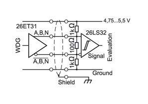
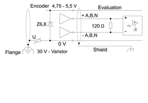
4,75 VDC up to 5,5 VDC
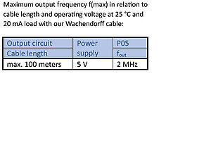
Current consumption: typ. 70 mA (100 mA only F05, P05)
Current consumption: typ. 70 mA (100 mA only F05, P05)
5 VDC up to 30 VDC
Current consumption: typ. 70 mA
Current consumption: typ. 70 mA
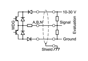
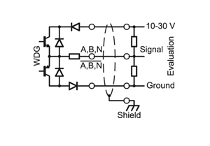
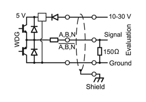
10 VDC up to 30 VDC
Current consumption: typ. 70 mA (100 mA only F24, P24, 645)
Current consumption: typ. 70 mA (100 mA only F24, P24, 645)
Environmental data
ESD (DIN EN 61000-4-2):
8 kV
Burst (DIN EN 61000-4-4):
2 kV
includes EMC:
DIN EN 61000-6-2
DIN EN 61000-6-3
Vibration:
(DIN EN 60068-2-6)
50 m/s2 (10 Hz up to 2000 Hz)
Shock:
(DIN EN 60068-2-27)
1000 m/s2 (6 ms)
Electrial Safety:
according DIN VDE 0160
Duty information
Customs tariff number:
90318020
Country of origin:
Germany
Operating temperature
-20 °C up to +80 °C [ -4 °F up to +176 °F]
1 Vpp: -10 °C up to +70 °C [+14 °F up to +158 °F]
1 Vpp: -10 °C up to +70 °C [+14 °F up to +158 °F]
Protection class
IP67+IP69K all around. Resistance to salt mist (IEC 60068-2-11) after 672 hours.

| Description | ABN inv. poss. | |
|---|---|---|
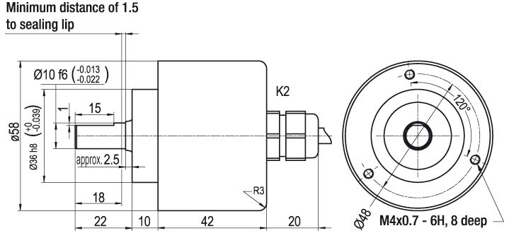
| K2 | axial, shield not connected | ● |
| L2 | axial, shield connected to encoder housing | ● |
Assignments
| K2, L2 | K2, L2 | L2 | |
| Circuit | F05, H05, F24, H24, H30 | P05, R05, P24, R24, 645, R30 | SIN |
| GND | WH | WH | WH |
| (+) Vcc | BN | BN | BN |
| A | GN | GN | GN |
| B | YE | YE | GY |
| N | GY | GY | - |
| - | - | - | - |
| A inv. | - | RD | YE |
| B inv. | - | BU | PK |
| N inv. | - | VT | - |
| Shield | flex | flex | flex |

| Description | ABN inv. poss. | |
|---|---|---|
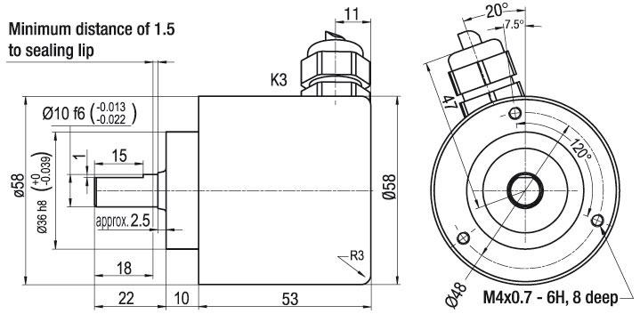
| K3 | radial, shield not connected | ● |
| L3 | radial, shield connected to encoder housing | ● |
Assignments
| K3, L3 | K3, L3 | L3 | |
| Circuit | F05, H05, F24, H24, H30 | P05, R05, P24, R24, 645, R30 | SIN |
| GND | WH | WH | WH |
| (+) Vcc | BN | BN | BN |
| A | GN | GN | GN |
| B | YE | YE | GY |
| N | GY | GY | - |
| - | - | - | - |
| A inv. | - | RD | YE |
| B inv. | - | BU | PK |
| N inv. | - | VT | - |
| Shield | flex | flex | flex |
up to 2500 PPR


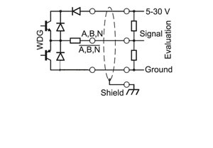
Power supply VDC
5 - 30 VDC
Current consumption
typ. 70 mA
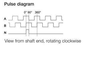
Signal shape
square-wave
Output circuit
HTL (TTL at 5 VDC)
Channels
AB, ABN
Output
push-pull
Load
max. 40 mA / channel
Signal level mA
at 20 mA
Signal level H>
H > Vcc -10% Vcc
Signal level L<
L < 2.5 VDC
Output frequency
max. 200 kHz
Circuit protection
inverse-polarity protection only
Light reserve warning
no

Power supply VDC
5 - 30 VDC
Current consumption
typ. 70 mA
Signal shape
square-wave
Output circuit
HTL, inv. (TTL/RS422 comp. at 5 VDC)
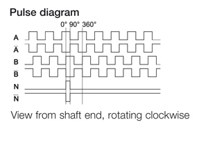
Channels
AB, ABN, and inverted signals
Output
push-pull
Load
max. 40 mA / channel
Signal level mA
at 20 mA
Signal level H>
H > Vcc -10% Vcc
Signal level L<
L < 2.5 VDC
Output frequency
max. 200 kHz
Circuit protection
inverse-polarity protection only
Light reserve warning
no
up to 5000 PPR
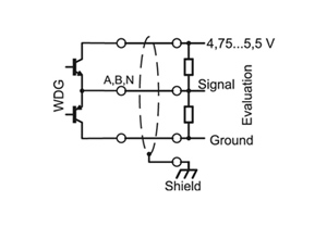

Power supply VDC
4.75 - 5.5 VDC
Current consumption
typ. 70 mA
Signal shape
square-wave
Output circuit
TTL
Channels
AB, ABN
Output
push-pull
Load
max. 40 mA / channel
Signal level mA
at 20 mA
Signal level H>
H > 2.5 VDC
Signal level L<
L < 0.5 VDC
Output frequency
max. 200 kHz
Circuit protection
no
Light reserve warning
no

Power supply VDC
4.75 - 5.5 VDC
Current consumption
typ. 70 mA
Signal shape
square-wave
Output circuit
TTL, RS422 comp., inverted
Channels
AB, ABN, and inverted signals
Output
push-pull
Load
max. 40 mA / channel
Signal level mA
at 20 mA
Signal level H>
H > 2.5 VDC
Signal level L<
L < 0.5 VDC
Output frequency
max. 200 kHz
Circuit protection
no
Light reserve warning
no

Power supply VDC
10 - 30 VDC
Current consumption
typ. 70 mA
Signal shape
square-wave
Output circuit
HTL
Channels
AB, ABN
Output
push-pull
Load
max. 40 mA / channel
Signal level mA
at 20 mA
Signal level H>
H > Vcc -2.5 VDC
Signal level L<
L < 2.5 VDC
Output frequency
max. 200 kHz
Circuit protection
yes
Light reserve warning
no
Power supply VDC
10 - 30 VDC
Current consumption
typ. 70 mA
Signal shape
square-wave
Output circuit
HTL inverted
Channels
AB, ABN, and inverted signals
Output
push-pull
Load
max. 40 mA / channel
Signal level mA
at 20 mA
Signal level H>
H > Vcc -2.5 VDC
Signal level L<
L < 2.5 VDC
Output frequency
max. 200 kHz
Circuit protection
yes
Light reserve warning
no
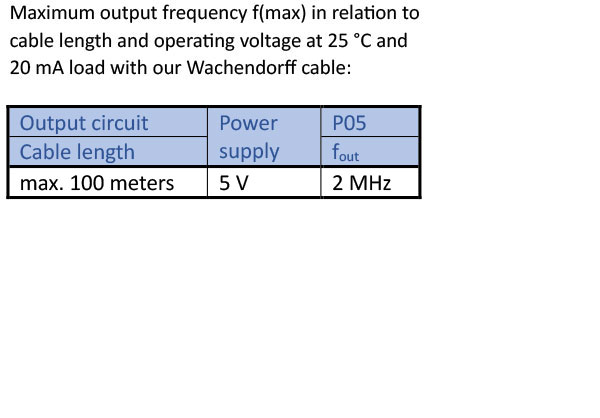
(higher frequency) 1200 up to 25000 PPR

Power supply VDC
4.75 - 5.5 VDC
Current consumption
typ. 100 mA
Signal shape
square-wave
Output circuit
TTL
Channels
AB, ABN
Output
push-pull
Load
max. 40 mA / channel
Signal level mA
at 20 mA
Signal level H>
H > 2.5 VDC
Signal level L<
L < 0.5 VDC
Output frequency
max. 2 MHz
Circuit protection
no
Light reserve warning
no
Power supply VDC
4.75 - 5.5 VDC
Current consumption
typ. 100 mA
Signal shape
square-wave
Output circuit
TTL, RS422 comp., inverted
Channels
AB, ABN, and inverted signals
Output
push-pull
Load
max. 40 mA / channel
Signal level mA
at 20 mA
Signal level H>
H > 2.5 VDC
Signal level L<
L < 0.5 VDC
Output frequency
max. 2 MHz
Circuit protection
no
Light reserve warning
no

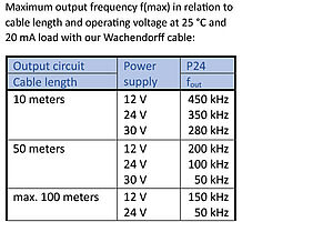
Power supply VDC
10 - 30 VDC
Current consumption
typ. 100 mA
Signal shape
square-wave
Output circuit
HTL
Channels
ABN
Output
push-pull
Load
max. 40 mA / channel
Signal level mA
at 20 mA
Signal level H>
H > Vcc -2.5 VDC
Signal level L<
L < 2.5 VDC
Output frequency
max. 600 kHz
Circuit protection
yes
Light reserve warning
no
Power supply VDC
10 - 30 VDC
Current consumption
typ. 100 mA
Signal shape
square-wave
Output circuit
HTL inverted
Channels
AB, ABN, and inverted signals
Output
push-pull
Load
max. 40 mA / channel
Signal level mA
at 20 mA
Signal level H>
H > Vcc -2.5 VDC
Signal level L<
L < 2.5 VDC
Output frequency
max. 600 kHz
Circuit protection
yes
Light reserve warning
no

Power supply VDC
10 - 30 VDC
Current consumption
typ. 100 mA
Signal shape
square-wave
Output circuit
TTL, RS422 comp., inverted
Channels
AB, ABN, and inverted signals
Output
push-pull
Load
max. 40 mA / channel
Signal level mA
at 20 mA
Signal level H>
H > 2.5 VDC
Signal level L<
L < 1.2 VDC
Output frequency
max. 2 MHz
Circuit protection
inverse-polarity protection only
Light reserve warning
no
1024, 2048 PPR
Power supply VDC
4.75 - 5.5 VDC
Current consumption
typ. 100 mA without load
Signal shape
sinus
Output circuit
1 Vpp sin/cos
Channels
AB
Output
Sinus, Cosinus
Load
@ 1 Vpp sin/cos: min. 120 Ohm
Signal level
1 Vpp +/- 25 %
Output frequency
max. 100 kHz
Circuit protection
no
Cabel lenght max.
max. 150 m at <260 pF/m
Light reserve warning
no
The encoder WDG 58S with the output circuit types F24, H24, P24, R24, F05, P05, 245, 645 is also available with the extended temperature range -40 °C up to +80 °C [-40 °F up to +176 °F] (measured at the flange).
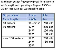
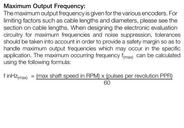
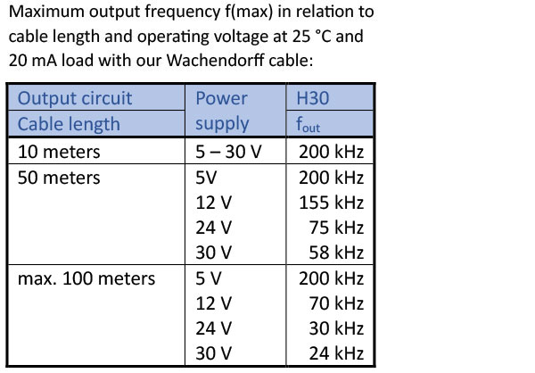
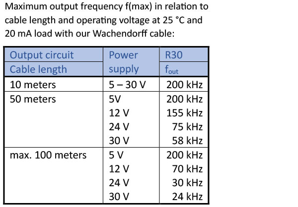
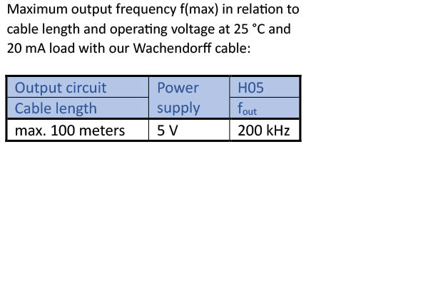
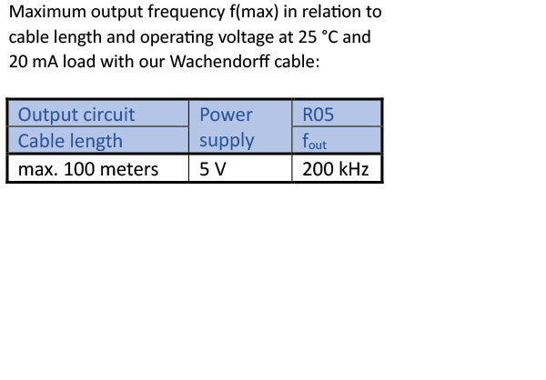
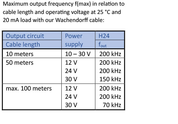
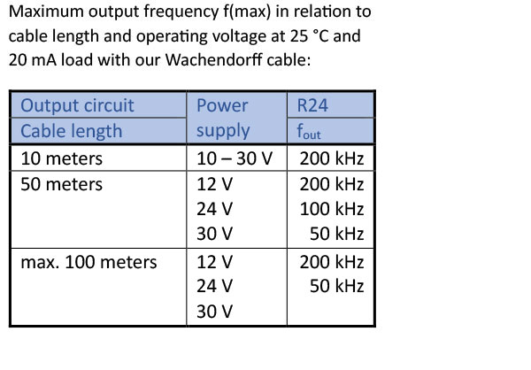
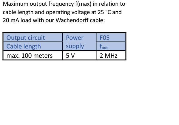
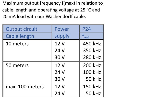
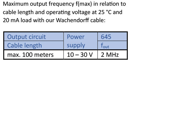
The encoder WDG 58S can be supplied with more than 2 m cable. The maximum cable length depends on the supply voltage and the frequency; see 'General Technical Data'
Please extend the standard order code with a three figure number, specifying the cable length in decimetres.
Example: 5 m cable = 050
Please extend the standard order code with a three figure number, specifying the cable length in decimetres.
Example: 5 m cable = 050


Short-Catalogue Encoders and systems
- Incremental and absolute encoders
- Digital shaft copying
- Made in Germany
- Motorfeedback
- Position Measurement Systems


For further information please contact our local distributor.
Here you find a list of our distributors worldwide
Here you find a list of our distributors worldwide
You want to get an offer or want a recall. Request