deenfresitcntr
WDGI 36E

Hollow bore (blind) encoder, magnetic,
Resolution: up to 1024 ppr,
Housing: Ø 36 mm

Hollow bore blind: Ø 6 mm, Ø 1/4" (6.35 mm);
Signal shape: square-wave.

Data sheet General technical data incremental encoders (PDF 855 kB)
Drehgeber Encoder WDGI36E
Highlights
  • Compact and robust
  • All pulse numbers from 1 to 1,024 I/U available
  • Robust construction for industrial use
  • Protection to IP67, shaft sealed to IP65
Product details
Flange
hollow shaft (blind-bored)
Pulses per revolution PPR
1-1024
Housing
Ø 36 mm
stainless steel
Shaft
Ø 6 mm
Insertion depth min.: 8 mm
Insertion depth max.: 17 mm
Max. Permissible shaft loading radial: 80 N
Max. Permissible shaft loading axial: 50 N
Ø 6.35 mm, Ø 1/4"
Insertion depth min.: 8 mm
Insertion depth max.: 17 mm
Max. Permissible shaft loading radial: 80 N
Max. Permissible shaft loading axial: 50 N
Max. operating speed
12000 rpm
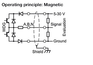
Output circuit
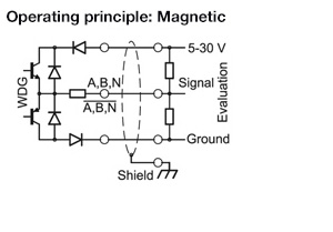
HTL (TTL at 5 VDC)
HTL, inv. (TTL/RS422 comp. at 5 VDC)
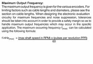
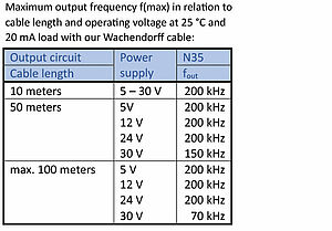
Output frequency
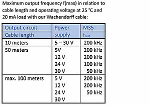
≤ 1024 ppr, max. 200 kHz
Power supply
5 VDC up to 30 VDC
Current consumption: typ. 40 mA

Environmental data

ESD (DIN EN 61000-4-2):

8 kV

Burst (DIN EN 61000-4-4):

2 kV

includes EMC:

DIN EN 61000-6-2
DIN EN 61000-6-3

Vibration:
(DIN EN 60068-2-6)

50 m/s2 (10 Hz up to 2000 Hz)

Shock:
(DIN EN 60068-2-27)

1000 m/s2 (6 ms)

Design:

according DIN VDE 0160

Duty information

Customs tariff number:

90318020

Country of origin:

Germany

Operating temperature
Connector: -40 °C up to +85 °C, cable: -20 °C up to +80 °C, (Option ACA: -40 °C up to +85 °C)
Protection class
Housing: IP65, IP67; shaft sealed: IP65; cable outlet K1: IP40
STEP viewer / STEP data:

Your desired STEP file is not listed:
Request STEP file here

Description ABN inv. poss.
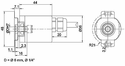
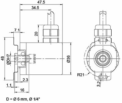
L2 axial, shield connected to encoder housing
Assignments
 L2L2
CircuitN35M35
GNDWHWH
(+) VccBNBN
AGNGN
BYEYE
NGYGY
Light reserve warning--
A inv.-RD
B inv.-BK, (BU at ACA)
N inv.-VT
Shieldflexflex
STEP viewer / STEP data:

Your desired STEP file is not listed:
Request STEP file here

Description ABN inv. poss.
L3 radial, shield connected to encoder housing
Assignments
 L3L3
CircuitN35M35
GNDWHWH
(+) VccBNBN
AGNGN
BYEYE
NGYGY
Light reserve warning--
A inv.-RD
B inv.-BK, (BU at ACA)
N inv.-VT
Shieldflexflex
STEP viewer / STEP data:

Your desired STEP file is not listed:
Request STEP file here

Description ABN inv. poss.
K1 radial, shield not connected (IP40)
Assignments
 K1K1
CircuitN35M35
GNDWHWH
(+) VccBNBN
AGNGN
BYEYE
NGYGY
Light reserve warning--
A inv.-RD
B inv.-BK
N inv.-VT
Shieldflexflex
STEP viewer / STEP data:

Your desired STEP file is not listed:
Request STEP file here

Description ABN inv. poss.
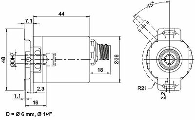
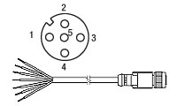
SB5 axial, 5-pin, Connector connected to encoder housing-
SB8 axial, 8-pin, Connector connected to encoder housing
Assignments
SB5SB8SB8
 5-pin8-pin8-pin
connector drawing
CircuitN35N35M35
GND311
(+) Vcc122
A433
B244
N555
Light reserve warning---
A inv.--6
B inv.--7
N inv.--8
n. c.-6, 7, 8-
Shield---
STEP viewer / STEP data:

Your desired STEP file is not listed:
Request STEP file here

Description ABN inv. poss.
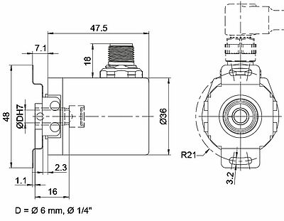
SC5 radial, 5-pin, Connector connected to encoder housing-
SC8 radial, 8-pin, Connector connected to encoder housing
Assignments
SC5SC8SC8
 5-pin8-pin8-pin
connector drawing
CircuitN35N35M35
GND311
(+) Vcc122
A433
B244
N555
Light reserve warning---
A inv.--6
B inv.--7
N inv.--8
n. c.-6, 7, 8-
Shield---
1-1024 PPR
Power supply VDC
5 - 30 VDC
Current consumption
typ. 40 mA
Signal shape
square-wave
Output circuit
HTL (TTL at 5 VDC)
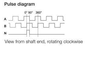
Channels
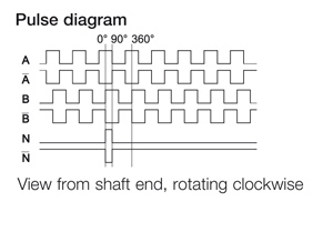
AB, ABN
Output
push-pull
Load
max. 40 mA / channel
Signal level mA
at 20 mA
Signal level H>
H > Vcc -10% Vcc
Signal level L<
L < 2.5 VDC
Output frequency
max. 200 kHz
Circuit protection
no
Light reserve warning
no
Power supply VDC
5 - 30 VDC
Current consumption
typ. 40 mA
Signal shape
square-wave
Output circuit
HTL, inv. (TTL/RS422 comp. at 5 VDC)
Channels
AB, ABN, and inverted signals
Output
push-pull
Load
max. 40 mA / channel
Signal level mA
at 20 mA
Signal level H>
H > Vcc -10% Vcc
Signal level L<
L < 2.5 VDC
Output frequency
max. 200 kHz
Circuit protection
no
Light reserve warning
no
The encoder WDGI 36E with the output circuit types M35, N35 is also available with the extended temperature range (measured at the flange).
The encoder WDGI 36E can be supplied with more than 2 m cable. The maximum cable length depends on the supply voltage and the frequency; see 'General Technical Data'
Please extend the standard order code with a three figure number, specifying the cable length in decimetres.
Example: 5 m cable = 050
General technical Data and safety instructions incremental encoders
General technical Data and safety instructions incremental encoders WDG/WDGI

Delivery times and service

of Wachendorff Automation GmbH & Co. KG

Assembly instructions hollow shaft encoders
Assembly instructions hollow shaft encoders WDG/WDGI

Whitepaper optisch und magnetisch Inkremental
Whitepaper


Comparison of optical and magnetic incremental encoders

CE_Konformitaetserklaerungen_M35N35
EU declaration of conformity output circuits M30/N30/M35/N35

UKCA-Konformitätserklärung
UKCA declaration of conformity output circuits M30/N30/M35/N35

UL Certificates for Wachendorff Automation Products 2014-03-28
UL Certificates

for Wachendorff Automation products.

REACH regulation
REACH- and RoHS regulation of the EU

Information

ISO Zertifikat DIN EN 9001:2015
ISO Certificate DIN EN 9001:2015

KI567 Drehgeber Kabeldose
KI-5-67

Female connector KI-5-67:
Suitable for encoder with sensor connector outlet SB5 and SC5, 5 pin, IP67

Ready-made shielded connection cable with female cable connector straight,
shield connected.
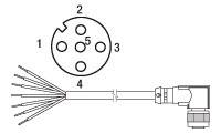
KIA567 Drehgeber Kabeldose
KIA-5-67

Female connector KIA-5-67:
Suitable for encoder with sensor connector outlet SB5 and SC5, 5 pin, IP67

Ready-made shielded connection cable with female cable connector angular,
shield connected.

KI867 Drehgeber Kabeldose
KI-8-67

Female connector KI-8-67:
Suitable for encoder with sensor connector outlet SB8 and SC8, 8 pin, IP67

Ready-made shielded connection cable with female cable connector straight,
shield connected.
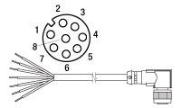
KIA867 Drehgeber Kabeldose
KIA-8-67

Female connector KIA-8-67:
Suitable for encoder with sensor connector outlet SB8 and SC8, 8 pin, IP67

Ready-made shielded connection cable with female cable connector angular,
shield connected.

WDGDS10016
WDGDS10016

Torque support WDGDS10016

for hollow shaft encoder 36E with hollow shaft (blind) Ø 6 mm.

WDGWA10M06 Drehgeber encoder Wellenadapter shaft adapter
WDGWA10M06

Shaft adapter WDGWA10M06

for thru-bore and hollow bore (blind) encoder Ø 10 mm
or couplings Ø 10 mm,
thread M6.

WDGWA10M08 Drehgeber Wellenadapter
WDGWA10M08

Shaft adapter WDGWA10M08

for thru-bore and hollow bore (blind) encoder Ø 10 mm
or couplings Ø 10 mm,
thread M8.

WDGWA10M10 Drehgeber Wellenadapter
WDGWA10M10

Shaft adapter WDGWA10M10

for thru-bore and hollow bore (blind) encoder Ø 10 mm
or couplings Ø 10 mm,
thread M10.

WDGWA10M12 Drehgeber Wellenadapter
WDGWA10M12

Shaft adapter WDGWA10M12

for thru-bore and hollow bore (blind) encoder Ø 10 mm
or couplings Ø 10 mm,
thread M12.

STEP file: external link​​​​​​​ WDGWA10M12.stp

WDGWA10M14 Drehgeber Wellenadapter
WDGWA10M14

Shaft adapter WDGWA10M14

for thru-bore and hollow bore (blind) encoder Ø 10 mm
or couplings Ø 10 mm,
thread M14.

WDGWA10M16 Drehgeber Wellenadapter
WDGWA10M16

Shaft adapter WDGWA10M16

for thru-bore and hollow bore (blind) encoder Ø 10 mm
or couplings Ø 10 mm,
thread M16.

STEP file: external link​​​​​​​ WDGWA10M16.stp

WDGWA10M20 Drehgeber Wellenadapter
WDGWA10M20

Shaft adapter WDGWA10M20

for thru-bore and hollow bore (blind) encoder Ø 10 mm
or couplings Ø 10 mm,
thread M20.

Generally encoder specifications

Incremental encoder specifications

Electrical connection

Cable outlet
Connector

Your configured order code

ShaftPPRChannelsOutputConnectionOption
WDGI 36E1-1024
distributors
For further information please contact our local distributor.
Here you find a list of our distributors worldwide
You want to get an offer or want a recall. Request